
INTRODUCTION
The ultrasound performed by a doctor who is treating a patient has multiple names, and it always reflects some of its main features. It can be called "clinical ultrasound" because it is an extension of the physical examination, and it is performed simultaneously to the patient's care. Unlike the ultrasound performed by the radiologist, it is functional and not anatomical. It is also named as "goal-directed" or “focused ultrasound”, since it is used for particular problem search, to try answering specific questions in a dichotomous way (yes or no). Moreover, “point-of-care ultrasound” or “bedside ultrasound" is perhaps the most popular name for being performed by the treating doctor, to find an immediate answer to a diagnostic or procedural need, while evaluating the performed treatments.
In addition to its immediate availability and autonomy, it offers advantages such as being portable and, especially in pediatrics, non-ionizing. On the contrary, the main disadvantage is its dependence on the performer's abilities. This problem and the possibility of incorrect interpretations, which can lead to inappropriate treatment of the patient, can be minimized thanks to a correct and not necessarily prolonged training. The continually increasing scientific evidence speaks in favour of its use, and it rapidly becomes essential for the clinician who starts using it.
The information you are about to study could be difficult to digest at the beginning. Please, understand that more than one reading could be required to integrate all the physical concepts. Allow yourself to have doubts and come back to this material for clarification. We believe that strong fundamental knowledge will make you learn faster and understand better.
Take your time!
PHISICAL PRINCIPLES
The sound is a type of wave that carries energy, not matter, from place to place. It is created by the vibration of a moving object and must travel through a medium (not vacuum). It is a mechanical and longitudinal wave (the particles move in the same direction as the wave)
From a practical and simple perspective, there are specific characteristics of the waves that should be taken into account: frequency, wavelength, amplitude and propagation speed.
1. Frequency (ƒ in Hz)

It is the number of cycles per second or hertz (Hz). Ultrasound waves have a ƒ above the hearing threshold (20Khz). Its diagnostic use varies from 1 to 20 MHz.
REMEMBER
High-frequency waves (multiple cycles/sec) generate a higher resolution image but have low penetration. Useful for exploring superficial structures like the lung.
Low-frequency waves (few cycles/sec) generate a lower resolution image but they penetrate deep. Useful for exploring deeper structures like the kidney.
2. Wavelength (λ in mm)
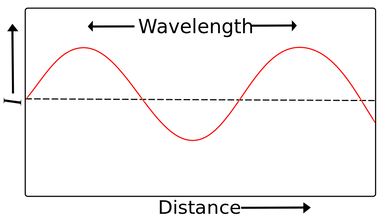
Is the distance between two identical adjacent points in a wave. It is typically measured between two easily identifiable points, such as two adjacent crests or troughs in a waveform. In diagnostic ultrasound, it ranges from 0.15 to 1.5mm.
4.Propagation speed (velocity)
Ultrasound machines assume that sound waves travel through the body at a constant speed of 1540 m/s. However, velocity is affected by the medium's density and elasticity. Propagation speed is different in each type of tissue.
v(constant)=ƒλ
A probe with higher frequency will have less wavelength (because the machine assumes that is constant at 1540 m/s).
Example: a linear probe is used to explore superficial structures.
THINK ABOUT IT !
Examples of propagation velocities in different tissues:
-
air: 330 m/sec
-
fat: 1450 m/sec
-
water: 1480 m/sec
-
liver: 1550 m/sec
-
kidney: 1560 m/sec
-
blood: 1570 m/sec
-
muscle: 1580 m/sec
-
bone: 4080 m/sec
REMEMBER
General rule
gas (slower) < liquid < solid (faster)
ULTRASOUND INTERACTIONS
When the ultrasound beam enters the tissue, it may be transmitted, reflected, refracted or attenuated. It is important to remember that an ultrasound probe is, at the same time, the sound sender and receiver.
1. Transmission
The ultrasound beam navigates through and between materials. When the soundwaves travel easily through uniform liquid substances such as water, oil or urine, no echoes are generated. The ultrasound image seen on the screen is, therefore, black. When the soundwaves encounter a tissue that absorbs or transmits the sound, a wave is reflected towards the probe. The ultrasound image will white or gray, depending on the amount of reflection.
2. Reflection

Also known as “echo”. It is the part of the ultrasound beam that returns to the transducer. The more reflection, the whiter or “echogenic” the image will be. It takes place in the interphase between two tissues with different acoustic impedance (how much resistance an ultrasound beam encounters as it passes through a tissue).

Percentage of reflection of the US in diverse body interphases:
3. Refraction

Bending of waves from one medium to another. It is the redirection of the US beam when incising obliquely an interphase of tissues with different features. It can create diverse artifacts (for example, mirror artifact). For example, if you tilt a probe while examining a patient's thorax, you could see more or fewer artifacts.
REMEMBER
The bigger the difference of acoustic impedance between two tissues is, the higher the reflection is, generating a whiter and brighter image on the screen (large amplitude/intensity echo).
Example: the pleura (soft tissue/air), stomach, intestinal loop, create a highly hyperrefringent image due to high acoustic impedance difference.
4. Attenuation
Energy loss experienced by the ultrasound beam while traveling through the tissues. It is due to reflection, refraction, scattering and absorption (by transforming the mechanical energy into thermal energy). The attenuation depends on:
-
Frequency: the higher the f, the higher the attenuation and the less the tissue is penetrated.
-
Acoustic impedance (acoustic resistance) between tissues
REMEMBER
“Echo” is the amount of ultrasound that is reflected (returns to the transducer) and depends on:
-
The incident angle of the ultrasound beam (hoy you position your probe!)
-
The impedance between tissues (medium interphase)
MORE REFLECTION (MORE “ECHOES”) HYPERECHOGENIC IMAGE (WHITE)
5. Bioeffects
The ultrasound is a form of energy so that when it passes through the tissues, it can be transformed into other types of energy. On the one hand, there is the mechanical energy (always indicated as MI on the ultrasound screen), called "cavitation". It produces air bubbles which can oscillate and explode due to the consequent tissue damage. On the other hand, there is the thermal energy (indicated as TI on the screen). It can be accounted for by the ultrasound absorption and the heat transformation. The latter ought to be kept in mind when performing an eye ultrasound.
IMAGE ACQUISITION

The transducer acts briefly as a sender (1/1000 parts of time) and mostly as a receiver or listener (999/1000). The ultrasound beams are sent as pulses periodically repeated on time allowing a silent time or "listening time". Pulse repetition frequency (PRF) indicates the number of ultrasound pulses emitted by the transducer over a designated period of time.
The ultrasound transducer has piezoelectric crystals that vibrate when they receive electricity, vibrating and generating a mechanical wave that generates the ultrasound beam. This ultrasound beam will travel through the body, reflecting and returning to the transducer as a mechanical wave (pressure) that will modify the piezoelectric crystals and again be translated to electricity.
The ultrasound scanner analyses two characteristics of the echoes (reflected wave) in order to generate an image:
-
Intensity determines brightness (more intensity --> more hyperechogenic)
-
Time determines depth.
This process takes place several times in a matter of milliseconds. The higher the frequency of the emitted US, the fewer is the penetration, but the higher is the definition of the obtained images.
THINK ABOUT IT ! How does the ultrasound machine perceive depth?

Distance 2> Distance 1 so we'll see object 2 deeper than object 1 in the monitor.
The ultrasound machine measures the time that the ultrasound beam needs to go and come back to the probe and estimates the depth. The faster the refleced beam is captured, the more superficial the object is seenon the screen.
ARTIFACTS
Artifacts are errors generated by the ultrasound scanner itself when interpreting received signs. They are produced due to physical processes that affect the interaction between the US and the tissues. They are highly relevant in the use of the US as a clinical diagnostic tool and not only in the thoracic ultrasound, where they are essential. If artifacts are not taken into account, they can confuse the operator.
-
Reverberation

It is caused by the sustained bounce of the US between two highly reflective interphases, creating bright and repeated lines with decreasing intensity and equidistant from the transducer (A lines).
REMEMBER
The higher impedance between pleura/air creates the reverberating artifact (A lines) that does not let us see any DEPTH!
2. “Ring-down”

It is produced when the US has an impact on water drops amongst air bubbles, making this drop vibrate and creating a continuous sound wave which is transmitted to the transducer. It then generates a continuous and underlying image in the ultrasound machine (for example, pulmonary B-lines).
3. Acoustic shadow

When the ultrasound beam reaches a structure that causes high attenuation, a hypoechoic or anechoic shadow is seen after this structure. This phenomenon can occur with bone and calcium lithiasis, among others.
4. Specular image:
It is generated by some oblique structures (diaphragm, pericardium) which are capable of refracting (divert) the US beam. This diverted beam returns to a more superficial structure and reflects its image. When the sign reaches the probe later than it should have from this structure, the ultrasound processes and displays it on the screen as if it was more profound. At the same time, the structure is also represented correctly in the monitor due to a correct reflection.
